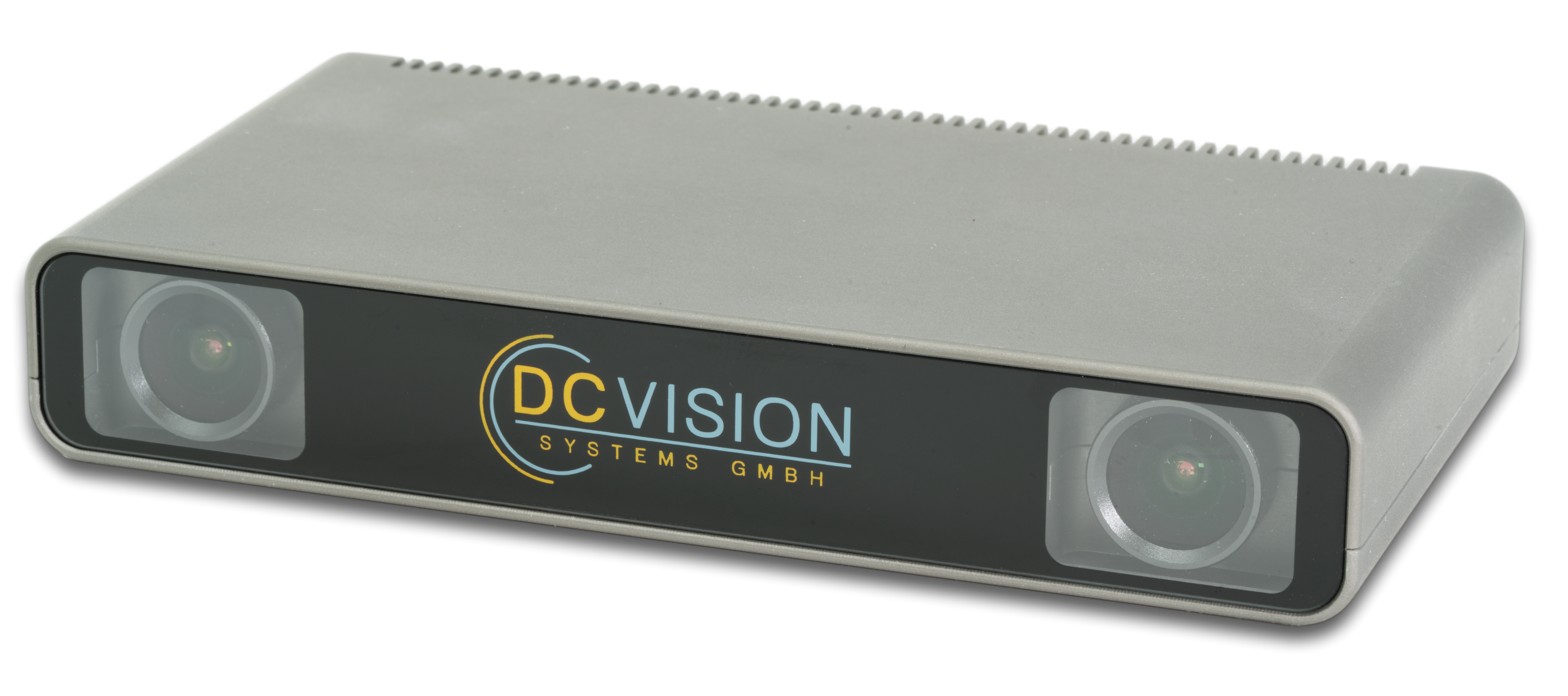
DC-SVP (Stereo Vision Processor) is an embedded vision camera capable of generating dense disparity maps with HD resolution in real-time with a frame rate of up to 25Hz without any external hardware using FPGA technology for algorithm acceleration. A fully featured Linux operating system runs on the camera and provides several support functions like networking, USB and a file system. On top of the OS, a server application controls the processing and implements data synchronization and online calibration. Depending on the customer needs, users can integrate additional applications which use the depth and image data on the camera. To access and display camera data on a host PC, an API and a viewer are provided for the user to easily communicate over the network. The demo application shows how to visualize image streams including the disparity map and how to calibrate and configure the camera from a host PC. The viewer can be used to visualize the data streams from the camera.
Key facts
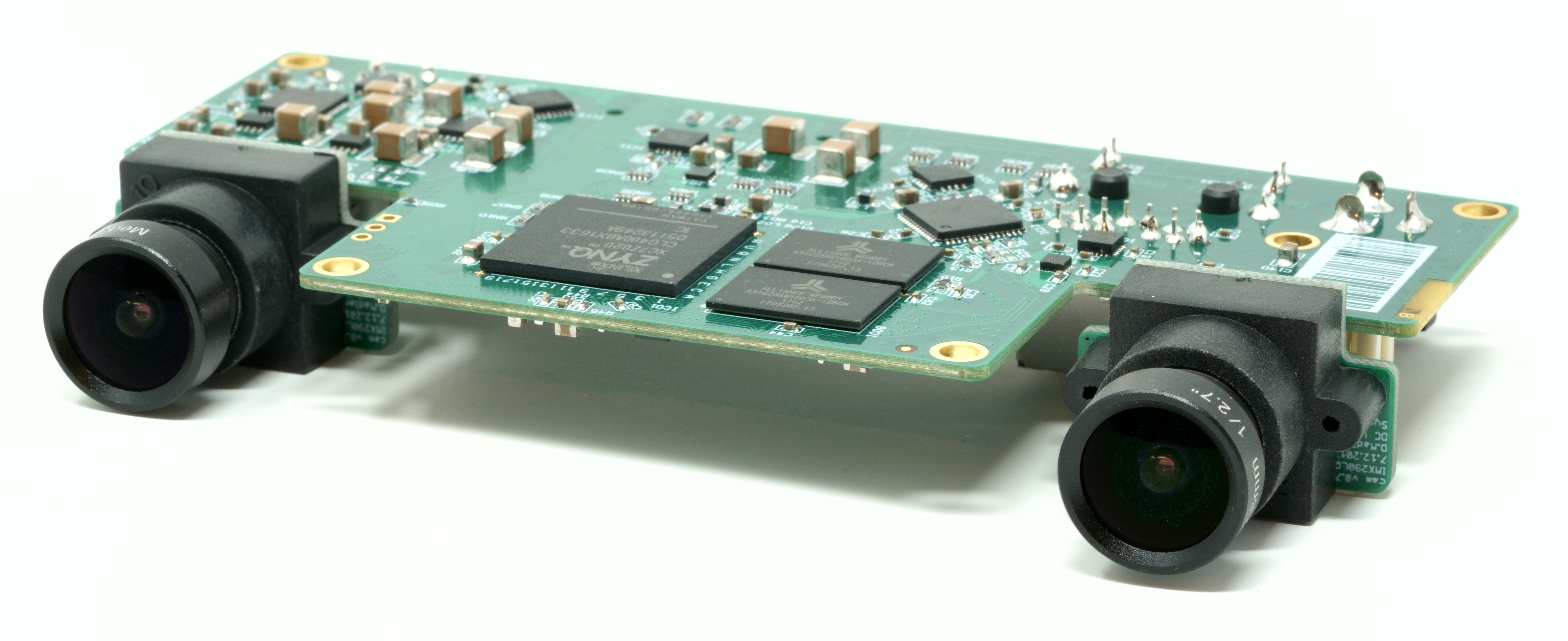
Embedded vision camera system utilizing a SoC with dual-core Cortex-A9 and FPGA logic
Proprietary stereo algorithm with superior stability, spacial and depth resolution
Online calibration for continuous optimization of the alignment running on the camera
No external processing necessary
Total power consumption less than 7W
Color processing pipeline
Real-time dense depth map output with
- 1280*720 pixels
- 128 disparities + subpixel
- 25 FPS
- Depth + confidence information, consistency checks
Stereo processing / Depth sensing
By simultaneous processing of two images from slightly different perspectives it is possible to measure depth information. Depth information can be used to measure the distance and position of objects relative to the camera. A simple application is free space detection for a mobile robot. From a single image and without additional information it is not possible to determine the distance of potential obstacles.
Depth information captured and processed with DC-SVP:
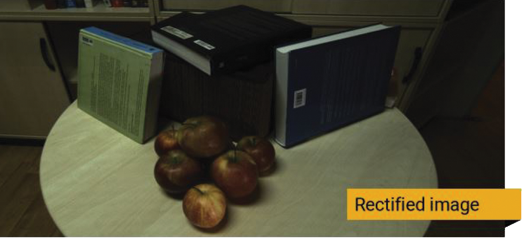
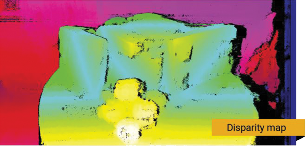
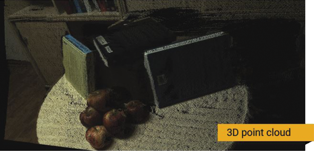
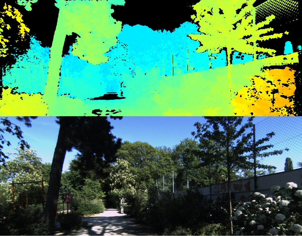
The figures above show an example of depth computation with DC-SVP. In the top/left one of the two (calibrated and rectified) images are shown. The middle image shows the color-coded output disparity map. The images and the depth map are generated in real-time on the device with no external processing required. The bottom/right shows a point cloud generated from the distance and the color image. The distance is used to project the color image pixels into 3D space. Therefore it is possible to render the scene from different perspectives. The last image shows an outdoor scene with color- and disparity-image.
System architecture & applications
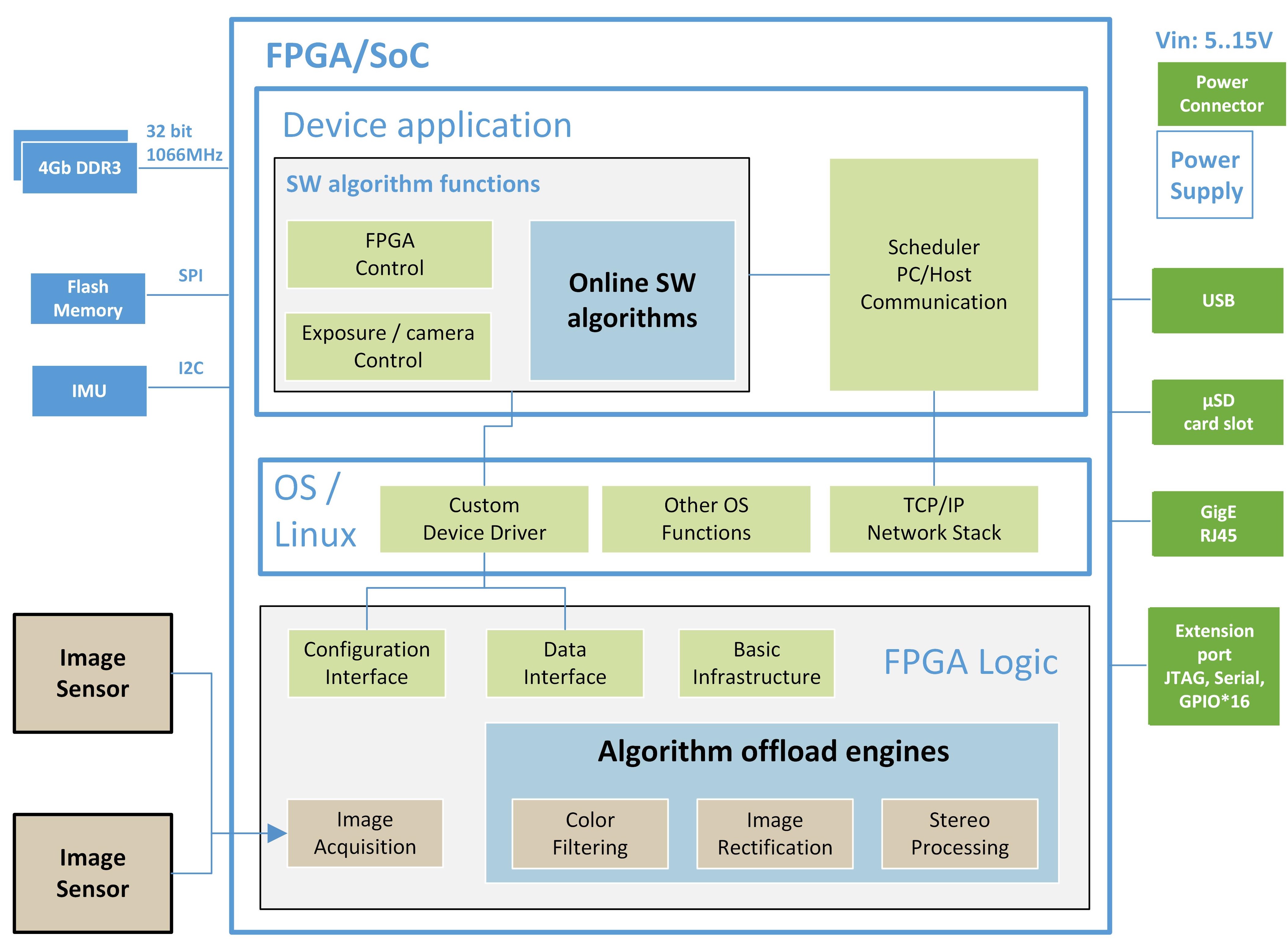
The overall system is built with a combination of hardware, software and firmware components. The software and the firmware run on a FPGA SoC which contains processor and FPGA-fabric subsystems. The partitioning is outlined in the following figure:
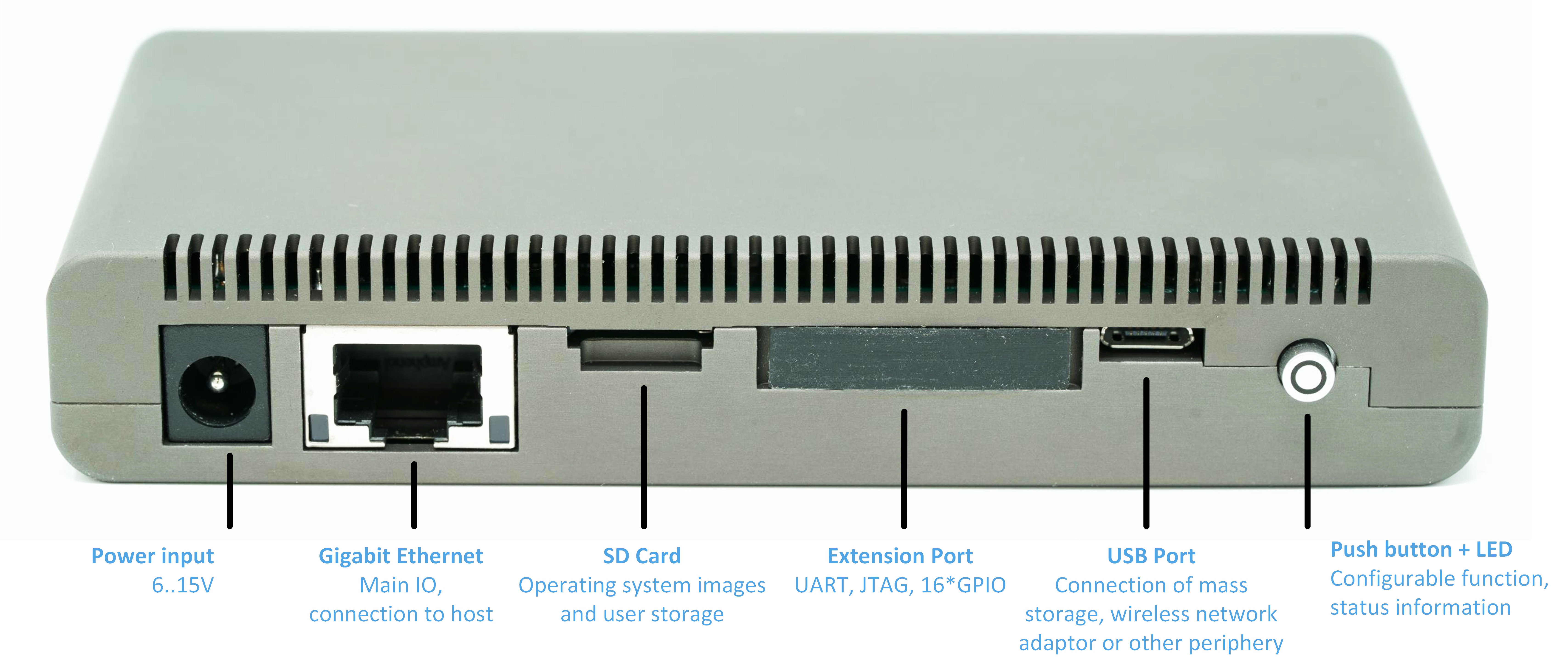
Interfaces
A host system can connect to the camera via the gigabit Ethernet interface with TCP/IP protocol. This ensures a reliable connection without the risk of frame drops because of lost packets.
Electronics